Electronic Hammer Technology
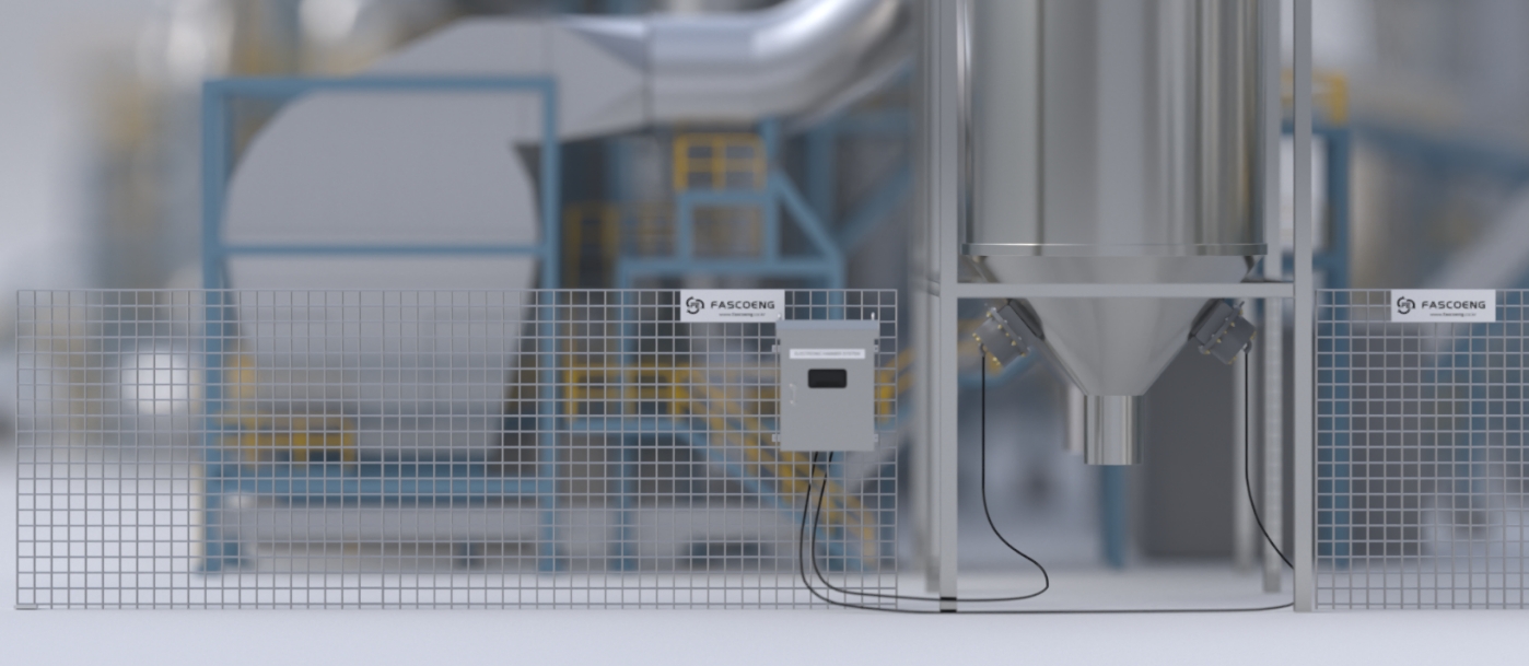
The driver that operates the electronic hammer is typically installed inside the electrical panel. It creates and transmits electrical signals for more effective operation of the electronic hammer and operates the electronic hammer with various safety devices.
Electronic Hammer System Technology
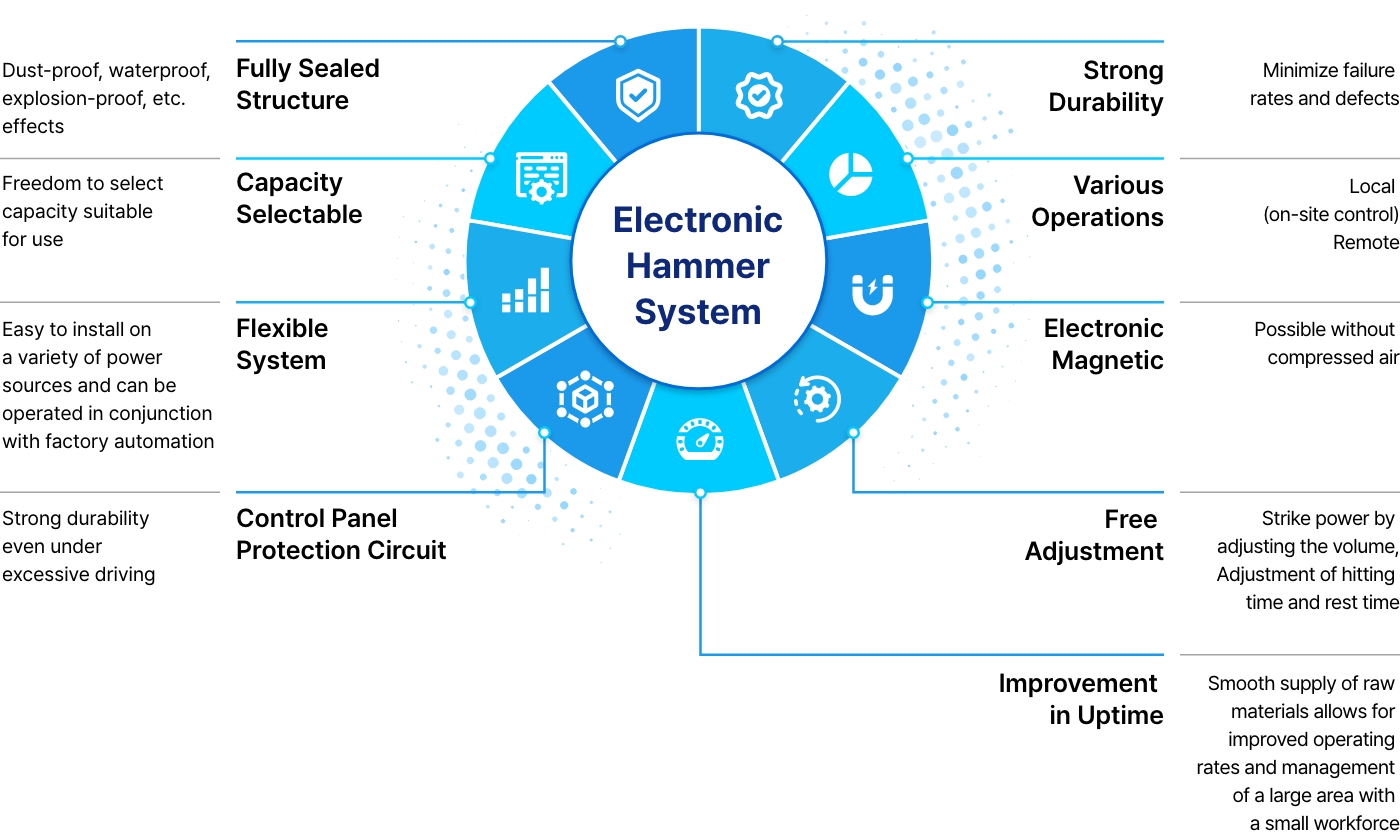
Function
- On-site control and remote control operation
- Multiple electronic hammers controlled
by a single controller
 Controller


Electronic Hammer Excellence
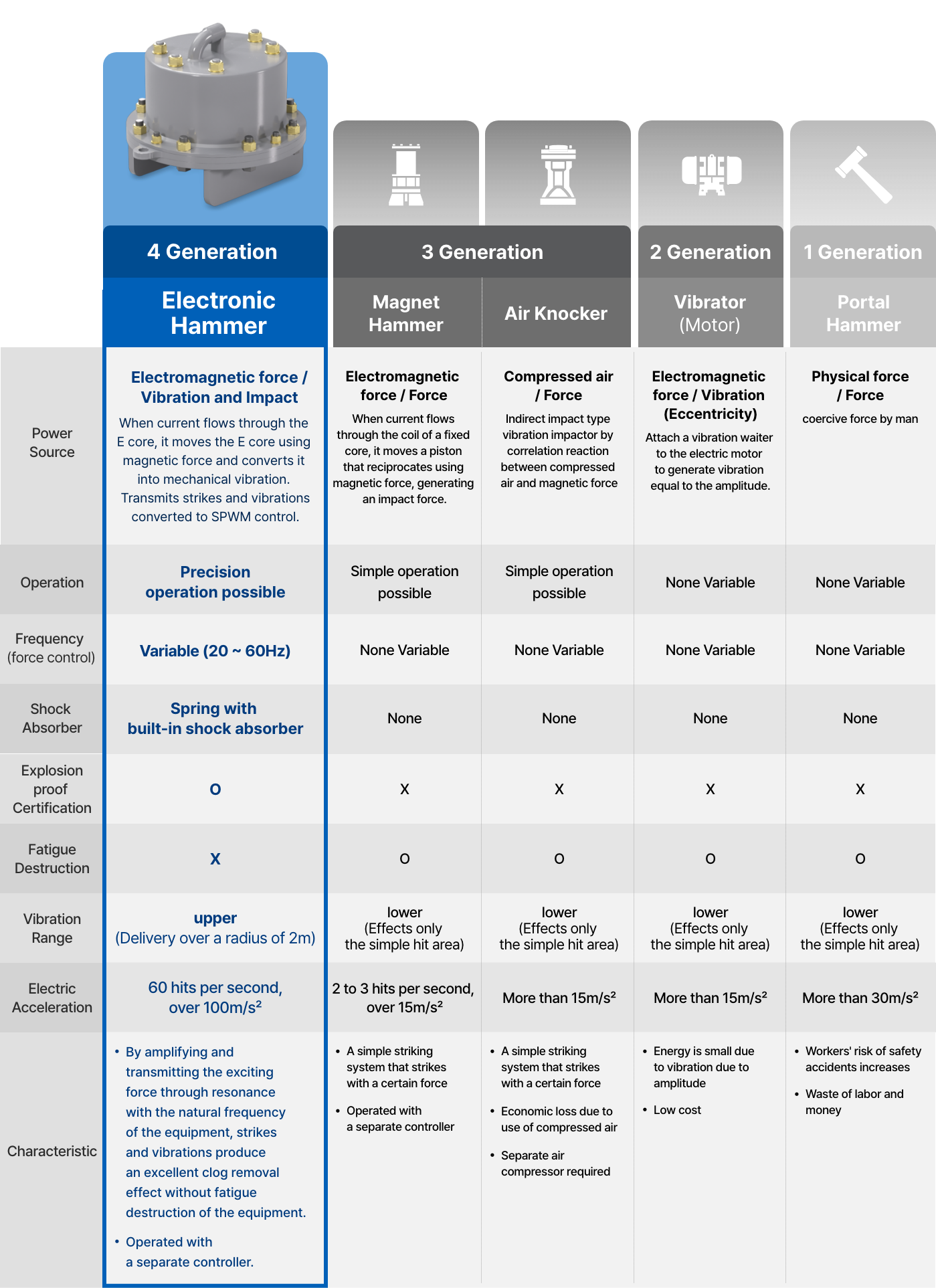
Electronic Hammer Solutions
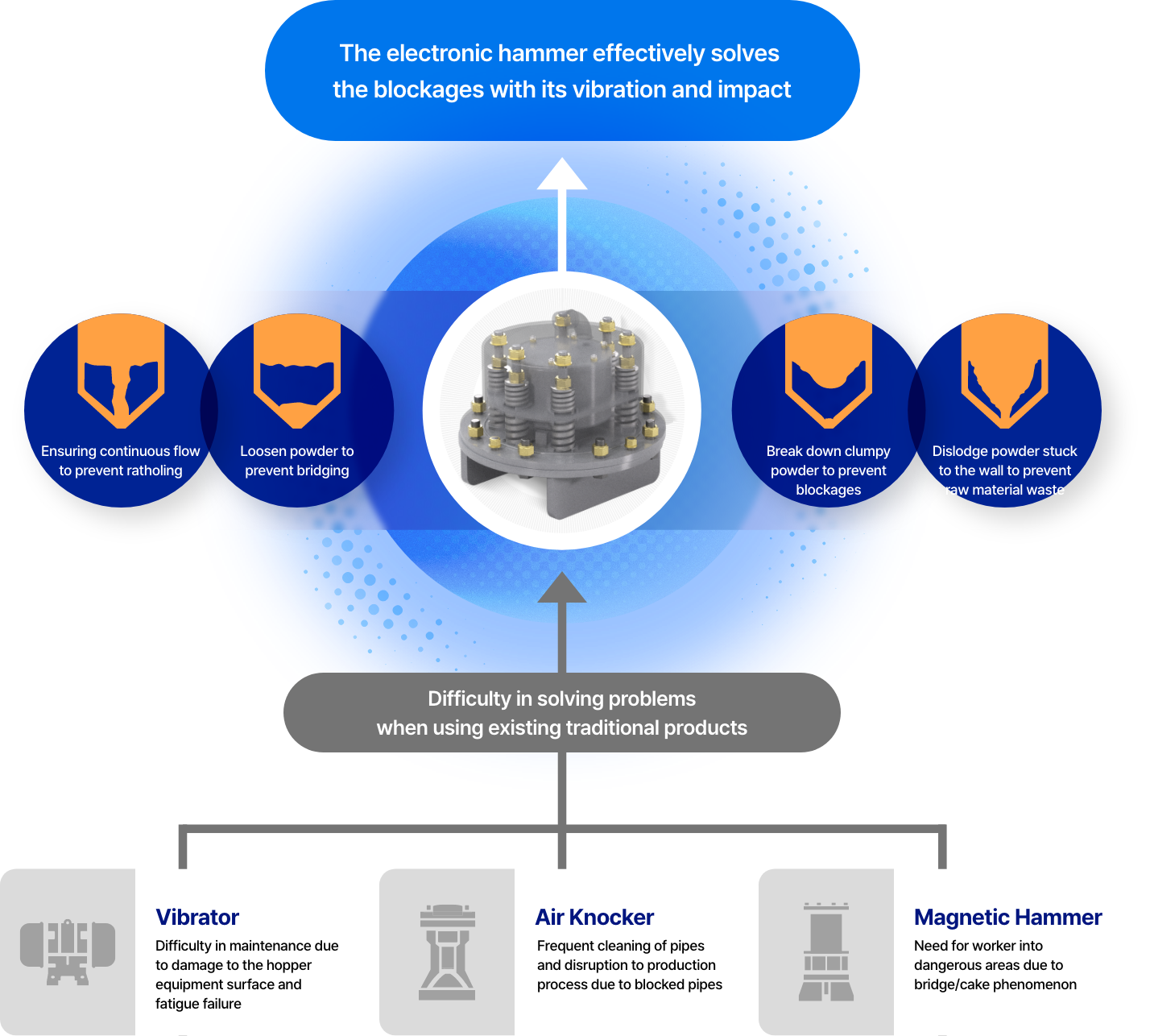
Electronic Hammer Features
-

Reduced Maintenance Costs & Improved Productivity Resolves powder deposits and caking/bridging blockages on inner walls, extending cleaning cycles and reducing maintenance costs.
-

Prevention of Labor Deterioration No direct impact on equipment surfaces to resolve blockages, preventing labor deterioration and equipment fatigue failure.
-

Safety
Accident Prevention Electronic hammers prevent safety accidents involving workers deployed to hazardous areas due to sudden blockages. -

Energy
Savings Simple installation with 220V power supply and excellent energy savings with low power consumption even during 24-hour operation.
System Principles
-
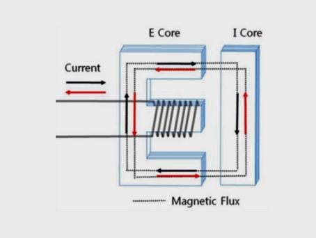 Electromagnetic Force Generation
When alternating current flows through the wire wound around the E-core, electromagnetic force is generated between the E-Core and I-Core by electromagnetic principles
-
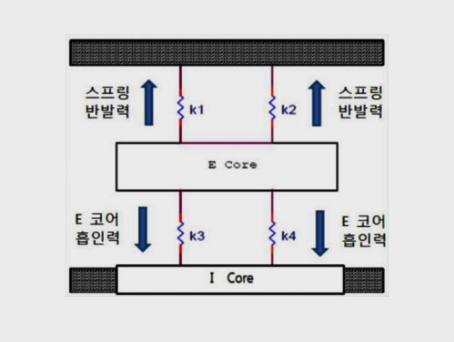 Mechanical Vibration Generation
Mechanical vibration and impact occur through the restoring force of elastic springs against electromagnetic force
-
 Vibration Radius
Delivers and amplifies momentary powerful impact and vibration to equipment surfaces, transmitting force to inner walls to prevent powder deposits and caking
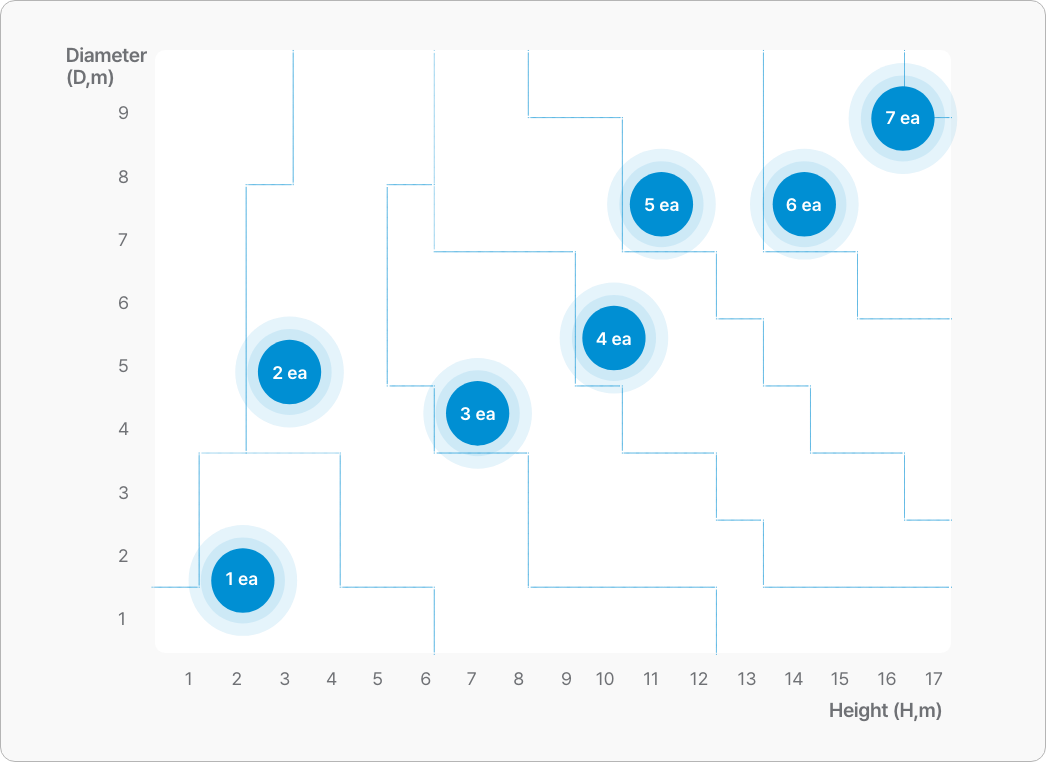
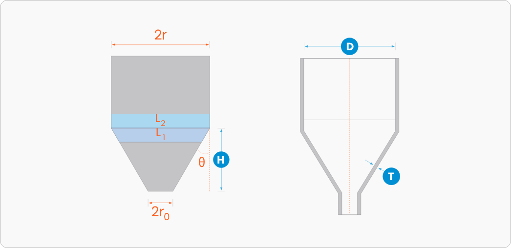
Specification Selection Criteria
Equipment Proportional Conditions
Models and quantities are selected based on diameter (D) and hopper plate thickness (T), with a hopper angle of repose of 60°. However, these may vary depending on hopper shape, powder properties, and conditions.
Installation
Quantity
Conditions
The chart below is based on 10mm thickness (T) and does not consider 2ro and L1, L2.
The number of hammer installations may vary depending on circumstances.